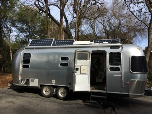
While progress has been being made on all fronts of the update of our 2005 Airstream CCD 25’ in the past couple weeks, getting the solar and inverter wiring finished has been the main priority. Having read numerous informative forum and blog posts on solar installations (particularly those of systems from AM Solar), I felt pretty confident (after a few false starts) mounting the panels on the roof and routing the wires through the combiner box and up to the front of the trailer. I was even ready to tackle the final solar connections through the cut-off switch, charge controller and up to the batteries via a few other do-dads that were all well-marked on the diagram included with the kit. It was the inverter wiring that got me…
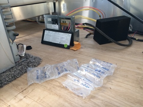
It didn’t help that my nerves were a bit shot after accidentally popping on one of these air pack things with my foot and thinking I was being electrocuted.
There are two types of power in the trailer: AC (alternating current, like that found in your house) and DC (direct current, think car battery). Items like the radio, lights, water pump, the Fantastic Fans and the furnace blower run on DC power from the batteries. When plugged into shore power, AC is routed to all outlets in the trailer as well as the air conditioner and the two-way fridge. This AC power is also converted (yup, by the “converter”) to DC to handle the load while the batteries are charging. An inverter goes the other direction, turning DC power into AC.
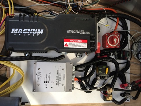
Our plan was to install a Magnum MMS1012 1000 Watt Inverter and wire it to provide AC power from the batteries to ALL outlets in the trailer. While even the factory inverter installation from Airstream only provides one (or two?) dedicated inverter outlets, and we were used to moving everything we needed to power next to our 300W portable inverter plugged into a 12V outlet in our 19’ trailer, in the larger trailer we wanted to be able to leave things like the camera battery charger, our phone chargers, and our toothbrush charger - not to mention network routers, boosters, the AppleTV and other entertainment and communications devices - plugged in right where they were even when running on battery power. None of these draw particularly much power, and with the addition of tools like a power strip with individually switched outlets we would be able to select which devices we wanted to be powered on to conserve energy. An added benefit was a much-improved “smart” charger built into the inverter to keep the batteries topped off. The manual said it was a 4 stage charger, but so far, I’ve only seen it go through anger, denial and guilt.
The wiring trick comes when trying to separating out the appliances we do not want powered by the inverter. A fridge running off of the battery would quickly deplete the batteries and the air conditioner would just about blow everything up. After days of staring at the AC panel and DC distribution box and pouring through forum posts, I decided that this was not a step I wanted to “wing it” on and called in a pro.
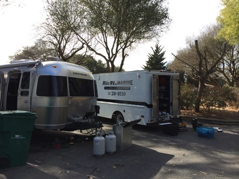
While I milled about in case he needed me to pass him a torque wrench or something (did I mention that I’m terrible at electrical?), he patched the air conditioner lead and a new wire running to a dedicated plug for the fridge into their own circuit(s?) which would be fed only when connected to shore power. He then separated the outlets out and routed them through the inverter, allowing them either to receive power from the batteries or shore power directly through a 20 amp AC pass through on the Magnum. It sounds straightforward (?!), but despite his bid of 7 hours (for two guys including completing the solar connections), he ended up coming back over the course of 3 days. To his credit, he honored the original bid and did a great job. Plus, made me feel like maybe I’d made the right decision not to tackle it myself.
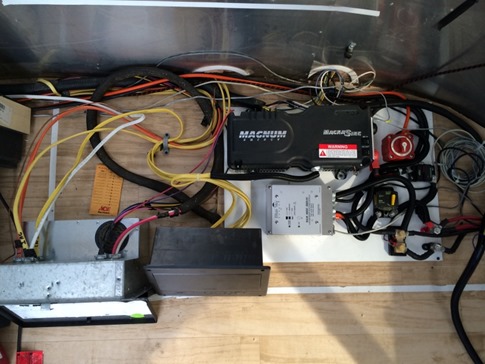
With the factory AC panel and DC distribution box (silver, bottom left) and a new AC panel for just the outlets (black plastic, bottom center) routed through the inverter. Note, I’ll need to cut a panel out of the side of the lounge underneath the pull out bed for access to the second panel.
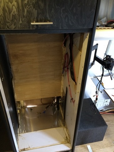
Now, I could finally clean up the fridge compartment, replacing some of the caulk and duct tape from the factory with decent cable ties and generally wiping up 8 years of dust that had come through the side and rooftop vents. Also, you can barely see the new dedicated fridge outlet in the lower right corner of the pic. We left the existing outlet (now on the inverter circuit) in place on the left side of the cabinet to make things easier. It could also be used as an exterior outlet on inverter power through the side vent if needed. Let’s just say you won’t want to be parked next to us at Christmas. “They’re beautiful, Clark!”
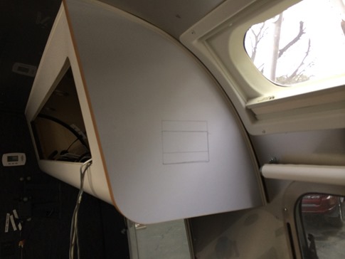
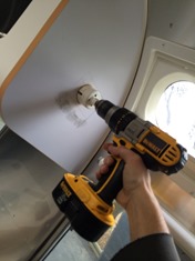
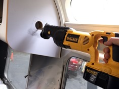
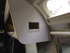
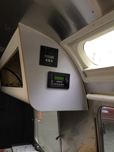
I also nervously got out my SawsAll and tore into the the cabinet above the dinette to make holes for mounting the remote control panels for the inverter and solar charge controller. Making the process all the more challenging was the fact that this side panel is 1 1/2” thick, made up of two pieces of 3/4” ply. Lots of sawdust and rattled arms, cabinets and nerves, but the results turned out pretty good.
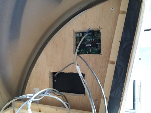
This backside will all be covered up by the 1/4” panels that line in the interior of the cabinets and the wiring running underneath in the chase used by the lights above the dinette.
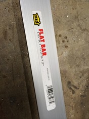
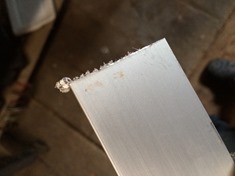
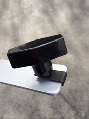
I ordered the standard mounting feet from AM Solar, so the last step was building a few more (6 total) tilting bars from a piece of flat aluminum. The rough edge from the cut-off blade on the chop saw cleaned up nicely with a file.
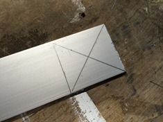
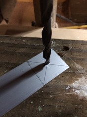
Marking the center and drilling the soft aluminum out on the drill press.
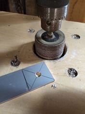
Rounding the edges with a sanding drum in the drill press and finishing off with some 1/4” threaded u-bolts and knobs from McMaster-Carr.
Now just unscrew two feet, tilt the panels and put the bars in place to support them. Oh, and move the trailer out of the shade of the barn and a 200 ft eucalyptus tree.
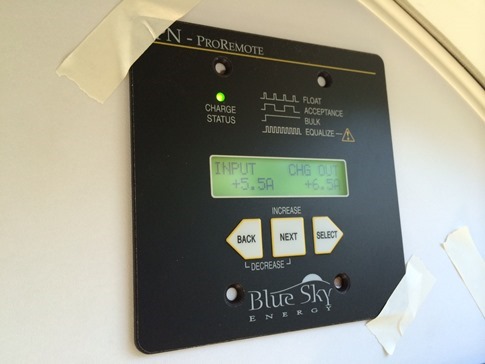
The first reading with decent afternoon (albeit Winter) sun, was about 9 amps coming in. With two panels about halfway shaded, I took the picture below with 5.5 amps. It’ll be interesting to get the trailer out into full sun and see what kind of readings we can get. Also to compare the values tilted and flat.
And don’t worry, this isn’t the final installation of the remote panel. I’m gonna use some nicer tape…

