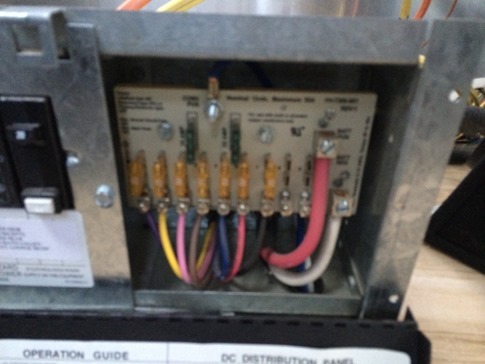
This picture is blurry, but I used it anyway because it accurately represents what I see when I look at an electrical panel. My eyes just refuse to focus, and my brain can’t wrap itself around what needs to be done. Fortunately, I still had to run the wires to the solar panels before I would even need to think about connecting into this bad boy.
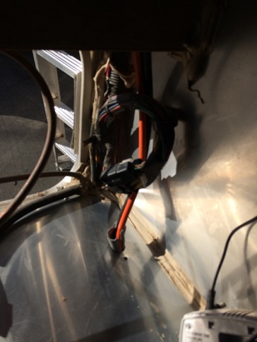
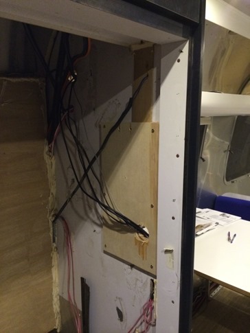
Despite having removed the whole couch and fridge to get easier access to the wiring, it was still a bit of a contortion to feed the thick 6 gauge wire under the dinette seat, on top of the wheel well and through a briar bush of electrical cables to where I could grab it through the compartment under the fridge in the hall.
I drilled a hole down through the aluminum sheet below the fridge compartment and was eventually able to thread the ends up into the sunlight. Then I realized that while I was running wire, I should probably also be feeding the wires for the two remote panels (an RJ-11 for the inverter and an RJ-11 and a power cord for the solar controller). I pulled the solar wire back out of the hole and widened it with the Dremel so it fit everything perfectly. Well, perfectly until I remembered that I also wanted to run an extra HDMI cable forward to the couch for playing movies from the laptop. so… pulled everything again, widened (again, this time with room to grow) and added the HDMI.
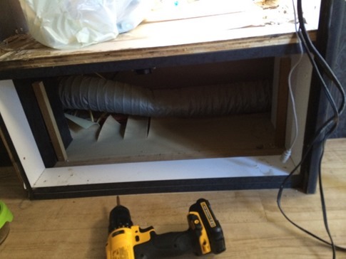
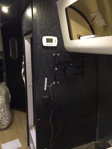
While I was in the fridge compartment, I added a piece of plywood to reinforce the wall where the new TV would hang and mounted the swing arm bracket and used a hole saw to drill out a 2” pass through that would be covered by a large cable grommet. The power cable for the new TV, two HDMI cables, the composite connectors running from the stereo that also plays DVD’s and the RCA audio cables running back to the stereo all fit so easily that I couldn’t resist mounting the TV. That’s when I discovered that the TV I’d bought – a rare but *perfect* size for the wall about the dinette – didn’t have an audio out of any kind. Not analog, not optical, not coax, not even headphone. Maybe not a big deal for some people, but the audio out is necessary to mute the speakers on the TV and route audio through the stereo speakers where they can be faded to either above the bed or above the lounge, away from wherever the baby is sleeping. The TV went back to the store, and I returned with the next size down (Ann tells me size isn’t important all the time) which had everything we needed.
Last bit of wiring in the fridge compartment was relocating the new digital thermostat which would have been hidden behind even the smaller TV.
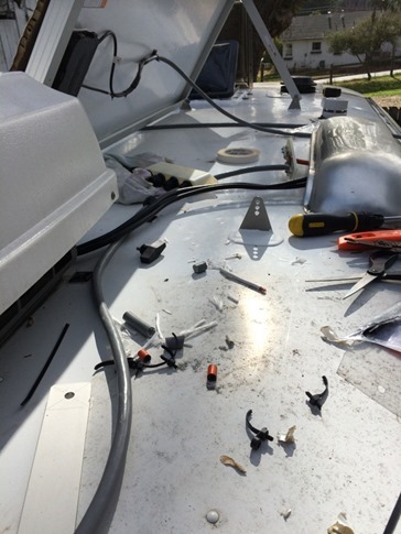
Back on the roof, I routed the cables from the panels to the combiner box at the fridge vent. Of course, since I’d cut the cables to length back when I thought they would all be placed in a line, a couple of them barely made it after accounting for the slack needed to allow them to tilt. Let’s just say, it took a few tries and several snipped zipties before I was able to make it work.
Working with the combiner box at the far side of the fridge vent was awkward to say the least. Add to that limited slack in my cables, a tight fit through the hole I’d drilled and 6 gauge wire, and let’s just say that words were used on the roof of that trailer I’m glad our two-year-old wasn’t around to learn.
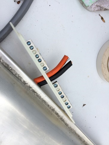
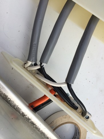
Yes, if you’re playing along at home, the picture below *is* wired backwards. Why in the world would I think the black wire would connect to the other black wire? How silly of me. Fortunately, I double-checked before closing everything up. The hardest part was exposing just the right amount of black and white wire to reach the correct slot on the bus bar while leaving the gray in the right position to pass through one of the four weatherproof anti-strain connectors on the combiner cover.
With that, it was time to go back in the trailer and figure out how to use my voltmeter to test the voltage and amperage. Now I should start by saying that California has been experiencing one of the driest Winters on record. As a result, I’ve been on the roof of the trailer in warm temps and direct sun for pretty much the entire month of January. As luck would have it, the high pressure system that has been occupying the Pacific chose to take a break that very afternoon. The clouds rolled in an shrouded my panels, robbing me of even the (unlikely) possibility of a victorious reading.
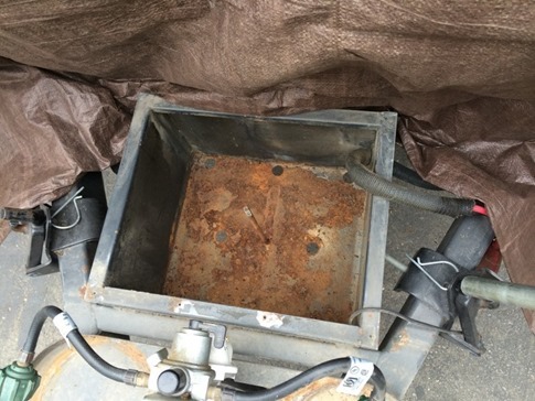
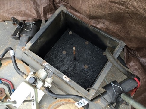
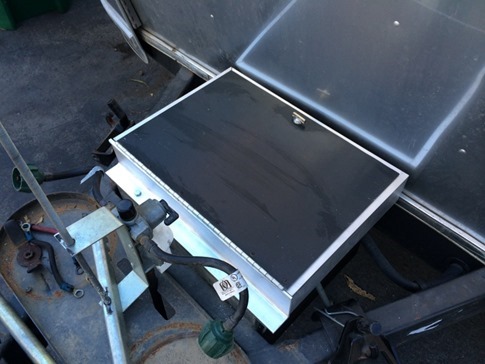
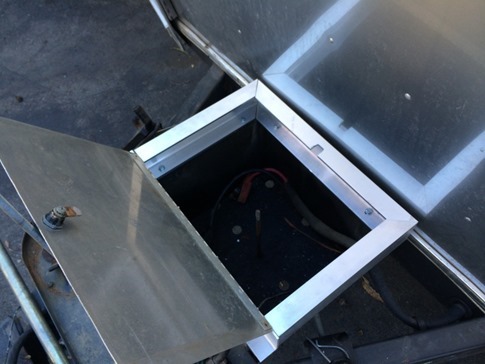
Clouded out, I went to work on modifying the battery compartment to accommodate the new larger 6V batteries, but when I pulled out the old 12V’s, the bottom of the compartment was a rusty mess. I briefly considered cutting out the old bottom and using it as opportunity to extend the battery compartment down instead of up. Despite the fact that the spare tire just behind the box would hang much lower than the new compartment, ground clearance concerns won out. The guy at the hardware store recommended a product called Rust Reformer that he said would actually chemically modify the flaking rust into new metal. I was ready to believe anything at that point, and the results look promising. Time will tell, but even if the bottom keeps rusting, it’s not like it’s gonna drop at all one time, and I can replace the bottom later if need be.
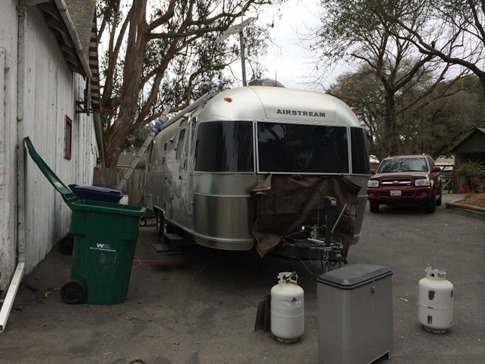
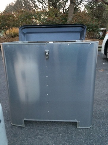
At this point, our beautiful new trailer was looking a bit the worse for wear…
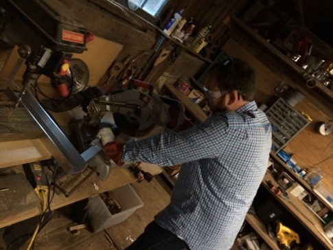
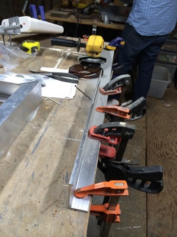
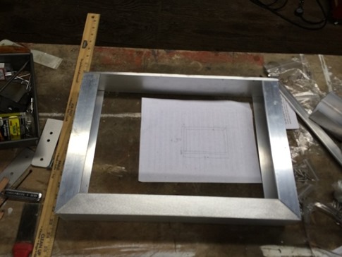
Returning to the plan of extending up, I’d taken the measurements of our particularly tall Trojan T-145’s and ordered some aluminum C channel from McMaster-Carr that would give us enough height. Whenever my friend Toby calls and says he wants to work on a manly project with me, I set him to work cutting metal. Last time was making a new set of gravity feeders for our pigs and this time was mitering the corners of the C channel on the chop saw with a cut off blade.
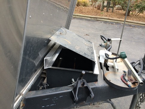
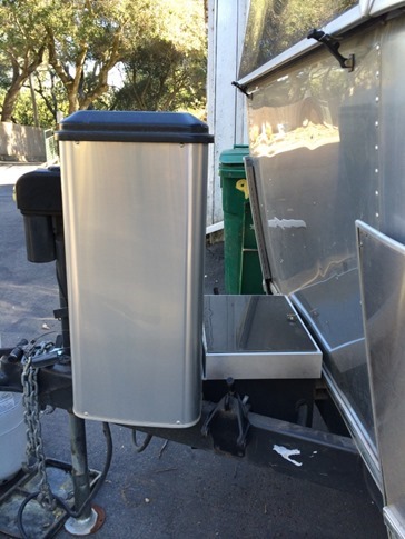
During our planning, we’d realized that the front piece would be tricky because of how the cover for the propane tanks went around the compartment. Note the notch below.
The solution was to turn this part of the C channel around and cut off one leg, making it more of an L channel. I barely cried at all while freehanding this cut with the grinder.
Ready to install!
Okay, maybe we didn’t measure *everything* twice… Luckily, I had decided to bolt the extension onto the battery box instead of riveting it just in case adjustments needed to be made. You know, like the ability for the lid to close without hitting the front of the trailer. That kinda thing. Cue more words Wynne shouldn’t hear…
But after some trimming on the band saw, problem solved and the other pieces went on.
Note the notch for the latch.
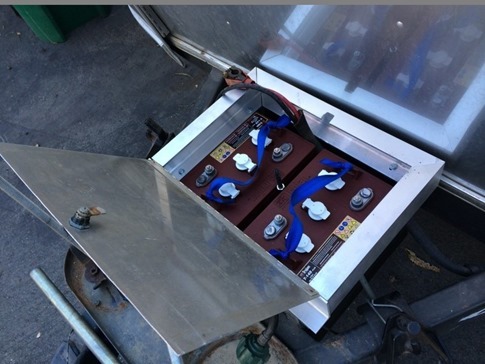
Batteries installed with plenty of headroom but not much room to spare. Note the 3/8” coupler and threaded extension to raise the height of the center clamp down.
What’s that you say? Impressive work from a skilled amateur? Factory look but better? I’m blushing…
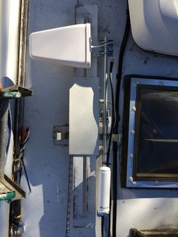
Sorry, at this point, I have to gloat a bit when something actually works. Case in point? Take a look at this slick antenna mounting setup. (Have you guessed by now that I’m avoiding the interior wiring?) After scouring the blogs of some of the full-timin’ “technomads” we traveled with up to Canada, I decided that two permanently mounted antennas, one for wifi and one for cellular, were the way to go. I opted for one omni and one directional figuring that we could mix and match with boosters and repeaters depending on the situation. The omni would work for a general boost, bringing a weak signal inside the aluminum tube, and the directional for grabbing wifi from across a campground or a cell signal from across the desert.
After careful measurement and detailed sketching, I discovered a way for both antennas to be mounted to the existing “batwing” TV antenna while retaining the ability to be deployed or retracted from inside. Okay, it was trial and error. There’s a little “bounce” while it goes down so I may lower the directional to reduce strain on the arm, but I think it looks pretty awesome even laid flat on the roof. Wait til you see it in the air…
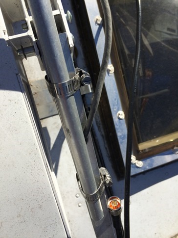
Directional is on a piece of aluminum rod attached to the top of the antenna arm with cable clamps. Omni is below attached to the arm with its included bracket. Antenna cables are run along side the skylight, around the AC and through the screen inside the fridge vent. They end up in the cabinet above the dinette where the networking equipment will be.
Behold… the deployment… [best when watched while humming the theme for “2001 A Space Odyssey”]

